A pixel-matrix status light that shows both a solid alert color and actual text (“IN MEETING”, camera icon, etc.), driven by AWTRIX NG firmware over MQTT into Home Assistant. This page is the build authority — if something here conflicts with a memory of how we did it, this page wins; fix the page, not the memory.
Parts list
Priced for lowest real cost, not Amazon-only — Amazon marks up generic-import electronics heavily, and a proper distributor (DigiKey) sells true single-unit quantities of passives for cents, not Amazon’s inflated multi-packs. Where a cheaper option ships slower (AliExpress, 2-4 weeks vs. Amazon’s 1-2 days), that tradeoff is called out plainly so it’s your call, not a hidden cost.
| Part | Qty needed | Best price | Price | Notes | |
|---|---|---|---|---|---|
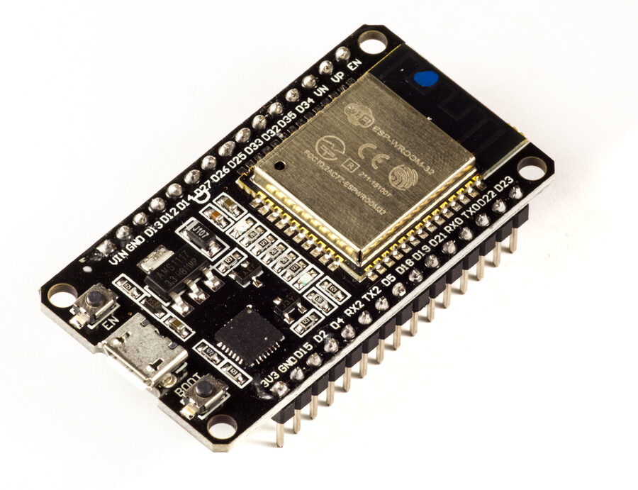 | ESP32-WROOM-32 DevKitC, USB-C, CP2102 | 1 | AliExpress, single unit | ~$4–6 | Classic 4MB ESP32 is fine — no need for ESP32-S3. All pin numbers in this guide are for this classic ESP32, not the S3. True single-unit price, but 2-4 week shipping. Faster alternative: HiLetgo 3-pack on Amazon, $12–15, arrives in days but is ~3x the per-unit cost. |
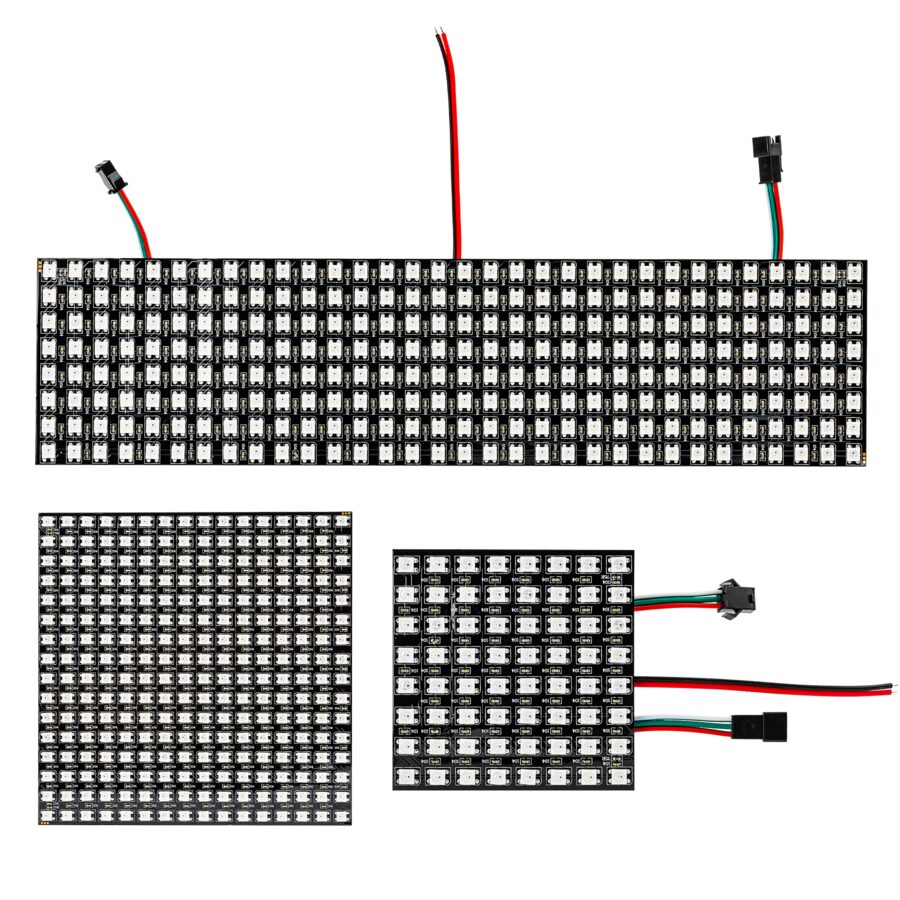 | WS2812B 8×32 flexible matrix panel, 256px, 5V | 1 | AliExpress, single unit | ~$4–5 | Same panel spec as the pricier Amazon listings, just without the import markup. Confirm the data-in arrow direction printed on the panel before wiring — it only accepts data one way. 2-4 week shipping; faster alternative: WESIRI on Amazon, $15–20. |
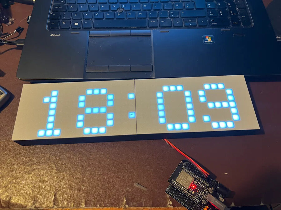 | 3D-printed case | 1 | 32×8 WS2812b Case (MakerWorld) — free STL | Free + print cost | Sized for this exact panel. No printer? A print service or local makerspace will run these small parts for a few dollars. Also grab a diffuser/faceplate model (search “AWTRIX diffuser” on Printables) — softens individual points into a proper pixel look. |
| — | 74AHCT125 logic level shifter, bare DIP-14 IC | 1 | DigiKey — SN74AHCT125N, true single-unit, MOQ 1 | ~$0.40 | WS2812 wants ~3.5V on DIN; ESP32 outputs 3.3V. DIP-14 solders directly into the perfboard below — no breakout board needed, which is most of why this is ~$5 cheaper than the Adafruit breakout. Same-day shipping from DigiKey. |
| — | Electrolytic capacitor, 1000µF, 25V | 1 | DigiKey — Rubycon 25PX1000MEFC10X16, true single-unit, MOQ 1 | ~$0.69 | Across 5V/GND at the panel’s power input. Smooths the power-on current surge — standard WS2812 practice. |
| — | Resistor, 330Ω, 1/4W | 1 | DigiKey — YAGEO CFR-25JB-52-330R, true single-unit, MOQ 1 | ~$0.10 | In series on the data line, at the board end, close to the ESP32’s GPIO pin. Protects against signal ringing/corrupted first pixel. Any value 330–470Ω works. |
| — | 5V/5A power supply, screw-terminal output | 1 | ALITOVE 5V 5A, on Amazon | $13–16 | Generic switching supplies like this are already commodity-priced — no meaningful savings found elsewhere. 5A gives headroom over the panel’s 3-4A draw at full brightness. Screw terminals mean no cutting/stripping a barrel plug. |
| — | 18 AWG hookup wire | ~1m | Striveday 18AWG, on Amazon | $8–10 | Sold only by the spool (25ft+) everywhere checked, not just Amazon — far more than this build needs, but no smaller-quantity source found. For the 5V/GND runs to the panel only; data line can use standard jumpers below. |
| — | Male-to-female jumper wires | ~5 | SinLoon 40-pack, on Amazon | $6–7 | Smallest dedicated M-F pack found anywhere. Signal/data wiring only, not the power runs. |
| — | Small perfboard | 1 | Tulead 2.4"×1.6", pack of 10, on Amazon | $7–9 | DigiKey sells single perfboard sheets but at a higher per-unit price than this 10-pack — Amazon is genuinely cheapest here even per-unit. Mounts the level shifter, resistor, and cap as one small soldered assembly. |
| — | USB-C to USB-A data cable | 1 | Amazon Basics, USB-IF certified | $6–8 | Must be a data cable, not charge-only, to flash the ESP32 — this one’s certified for 480Mbps data, not just power. |
Total: roughly $40–55 if you take the AliExpress board/panel and wait out the shipping; roughly $60–75 if you take the faster Amazon alternatives for those two lines instead. Either way, the DigiKey passives alone save real money over Amazon’s multi-packs — true single-unit pricing, no leftover spares you didn’t need.
Optional (not required for a status light)
| Part | Qty | Notes |
|---|---|---|
| Tactile buttons | up to 3 | Physical control — see pin table below. |
| LDR (photoresistor) | 1 | Auto-brightness based on ambient light, with a 10kΩ divider resistor. |
| Piezo speaker | 1 | Beep on notification. |
Tools needed
- Soldering iron + solder (basic through-hole joints only — no fine-pitch SMD)
- Wire strippers
- USB cable (data-capable) to flash the ESP32
- 3D printer, or access to one, for the case
- A computer with a browser (AWTRIX NG’s flasher is web-based, no toolchain needed)
Wiring — exact pins (classic ESP32 DevKitC)
These pin numbers are pulled directly from the AWTRIX NG hardware docs for the classic ESP32 (not the S3 — the S3 uses a different pin set entirely, don’t mix the two up if you search around for reference).
| Signal | ESP32 DevKitC pin | Connects to | Required? |
|---|---|---|---|
| Matrix data | GPIO 32 | 74AHCT125 input (A-side) | Required |
| Matrix data (level-shifted) | — | 74AHCT125 output (Y-side) → resistor → panel DIN | Required |
| Common ground | GND | 74AHCT125 GND, panel GND, PSU GND (all tied together) | Required |
| Button: Left | GPIO 26 | Button → GND (INPUT_PULLUP) | Optional |
| Button: Select | GPIO 27 | Button → GND (INPUT_PULLUP) — also the deep-sleep wake pin | Optional |
| Button: Right | GPIO 14 | Button → GND (INPUT_PULLUP) | Optional |
| LDR (light sensor) | GPIO 35 | 10kΩ divider to 3.3V/GND | Optional |
| Battery voltage monitor | GPIO 34 | 100kΩ/100kΩ divider | Optional |
| Buzzer | GPIO 15 | Piezo + | Optional |
| I2C SDA / SCL | GPIO 21 / GPIO 22 | Any I2C sensor add-on | Optional |
Everything below “Required” in that table can be skipped entirely for a status light — don’t wire it just because it’s in the table.
Wiring diagram
                                5V POWER SUPPLY (3-4A)
                         ┌─────────────────────────────┐
                         │   +5V                  GND   │
                         └────┬───────────────────┬─────┘
                              │                    │
                    18AWG     │                    │  18AWG
                              │                    │
                     ┌────────┴─────┐              │
                     │  1000µF cap   │              │
                     │  (+) ── (-)   │              │
                     └────┬─────┬───┘              │
                          │     │                   │
                          ▼     ▼                   ▼
                   ┌──────────────────────────────────────┐
                   │   WS2812B 8×32 PANEL                  │
                   │   5V ●        GND ●        DIN ●      │
                   └──────────────────────┬───────────────┘
                                           ▲
                                           │ (level-shifted data)
                                  ┌────────┴─────────┐
                                  │  74AHCT125        │
                                  │  VCC → 5V (PSU)    │
                                  │  GND → common GND  │
                                  │  A (in)   Y (out)  │
                                  └───┬───────────────┘
                                      ▲
                              [330-470Ω resistor]
                                      │
                               ┌──────┴──────┐
                               │  ESP32       │
                               │  GPIO 32 ────┤ (matrix data out)
                               │  GND ────────┤ (common ground —
                               │  USB (5V) ───┤  tie to PSU/panel/
                               └──────────────┘  shifter GND)
The single most important rule in this diagram: the panel’s 5V and GND come straight from the power supply, never routed through the ESP32 board. The ESP32’s own 5V pin/regulator cannot source the current a lit matrix panel needs — this is the #1 cause of random resets or a board that browns out under load.
The ESP32 itself can stay powered via its USB port throughout (both during flashing and normal operation) — it doesn’t need to share the panel’s beefier supply, it just needs to share its ground.
Build steps
- Print the case (or send the STL to a print service). Do this first — it’s the longest lead time item and needs zero babysitting once started.
- Dry-fit the matrix panel and ESP32 in the case before soldering anything, to confirm panel orientation and where cables need to exit.
- Solder the data path: ESP32 GPIO 32 → 330-470Ω resistor → 74AHCT125 input (A); 74AHCT125 output (Y) → matrix DIN.
- Solder power: PSU +5V/GND → 1000µF capacitor → matrix 5V/GND, using 18AWG for these runs. Separately tie ESP32 GND and 74AHCT125 GND into this same common ground.
- Flash AWTRIX NG using the web installer — plug the ESP32 in via USB, follow the on-screen flow. No compiler setup required unless you want to customize firmware source. In the installer/config, set the matrix data pin to 32 (classic ESP32 default).
- Power up and check orientation. If the display is mirrored, scrambled, or only half-lit, it’s almost always a data-in direction or GPIO pin mismatch — fix in AWTRIX NG’s config, not by re-wiring.
- Assemble into the case, add diffuser/faceplate.
- Wire into Home Assistant over MQTT — same broker
idoru-meeting-pollalready publishes to. AWTRIX NG exposes MQTT topics for text/color/notifications that map directly onto the existingstatus_light_meeting_on/status_light_meeting_offautomation logic.
Likely trouble spots (expect one of these, it’s normal)
- Flickering or wrong first-pixel color → almost always the missing level shifter or a bad data-line resistor value. Confirm the shifter is actually in the data path, not just power.
- Garbled/mirrored display → wrong data-in direction on the flexible panel, or the matrix data pin set to something other than GPIO 32 in AWTRIX NG’s config. Software fix (orientation/pin config), not a rewire, in most cases.
- Random resets under load → undersized power supply, or matrix power routed through the ESP32’s onboard regulator instead of directly from the PSU.
- Nothing lights up at all → check common ground between ESP32, level shifter, and matrix — this is the single most common “why is nothing happening” cause in WS2812 projects generally.
Reference links
- AWTRIX NG — Build your own (source for all pin numbers above)
- AWTRIX NG GitHub
- 32×8 WS2812b Case — MakerWorld
- 8×32 LED Matrix Case — Printables (alternate case design)
- WS2812B panel — BTF-Lighting
- 74AHCT125 level shifter — Adafruit
Difficulty, honestly: no single step here is hard. Soldering is basic through-hole joints, flashing is a web installer, and the case is a free download. The real time sink is the debugging loop when orientation or GPIO pin guesses are wrong on the first power-up — budget for one or two “why isn’t this working” sessions if this is a first LED-matrix project. Second time through, it’s a 2–3 hour build.
Component photo credits: ESP32 board photo by Ubahnverleih (CC0, via Wikimedia Commons); matrix case render from the MakerWorld model linked above.